Microcontroller projects
SmartyReader⁵
Reading 5 or 6 Luxembourgish smartmeter (P1 interface)
last updated: 29/01/18
Introduction
Because of the EU Energy Efficiency Directive from 2012 the seven gas and electricity DSO's in Luxembourg are replacing there gas and energy meters with smartmeters (named smarty :() til the end of 2019 (2020 for gas). Besides gas and electricity metering, the system is open for other metering data like water and district heat (M-Bus). The French group Sagemcom delivers the 305.000 smartmeters. All meters have to be read by one national central system, operated by a common operator. This is an economic group of interest (G.I.E.) of the 7 luxembourgish gas and electricity DSO‘s named Luxmetering G.I.E. Luxmetering is getting the data from 4 registers for active, reactive, import and export energy (1/4h) and the 3 registers for gas, water & heat (1 h) over PLC. The smartmeter have also alarms and logs for quality of electrical energy supply (voltage, outages,...) and fraud detection, and calendar functions for the 2 external relays (home applications).
The customer wants to get his data and this is possible by reading the blinking LED of the smartmeter. This can be done with the IoT-board (see end op page). Another possibility is the 10 second data from the smartmeter P1 port (RJ12 connector under the green lid). The P1 Data Output communication protocol and format is specified in the Dutch Smart Meter Requirements v5.0.2 . The solution deployed in Luxembourg includes an additional security layer standard that is conform to the IDIS package 2.0 requirement. The encryption layer is based on DLMS security suite 0 algorithm: AES128-GCM. More information can be found in this document.
P1 port
Hardware
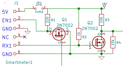
The P1 port connector is a 6 pole RJ12. We get 5V (250mA) on pin 1 (Power GND on pin 6, data GND on pin 3). Data pin 5 sends an inverted serial signal (EIA232) with 8N1. To get this data the data request µline (pin 2) has to be high (5V). Pin 4 is not connected. More details in the Dutch Smart Meter Requirements. As we use a microcontroller working on 3.3V we need a transistor to bring the voltage of the data line to 5V (Q1). The second transistor inverts the serial data to be EIA232 compliant. A voltage divider (R3, R4) brings the voltage down to 3.3V.
Encryption
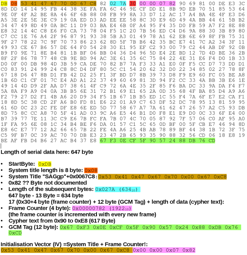
As stated the communication on P1 port is encrypted with AES128-GCM (Galois Counter Mode). Each meter has its own 16 byte encryption key. Ask your DSO or Luxmetering for your key. With the key we need the cypher text, 17 byte Additional Authenticated Data (AAD), a 12 byte Initialization Vector (IV) and a 12 byte GCM Tag. The AAD is fix: 0x3000112233445566778899AABBCCDDEEFF. The other data is extracted from the serial stream.
The Initialization Vector (12 byte) consists of the system title (8 byte) and the frame counter (4 byte). The GCM Tag is found at the end of the stream.
IoT and MQTT
The MQTT-protocol is a publisher/subscriber protocol and it is quite simple to implement this protocol on microcontrollers like the WeMos D1 mini board (ESP8266). The smartmeter data is published by the WeMos board over Wifi. It is necessary to run a message broker (server) to distribute the data. I use for this mosquitto on a raspberry pi. The WeMos board publishes the data and the same raspberry pi with the broker or another computer subscribes to the data and generates p. ex. a graphic.
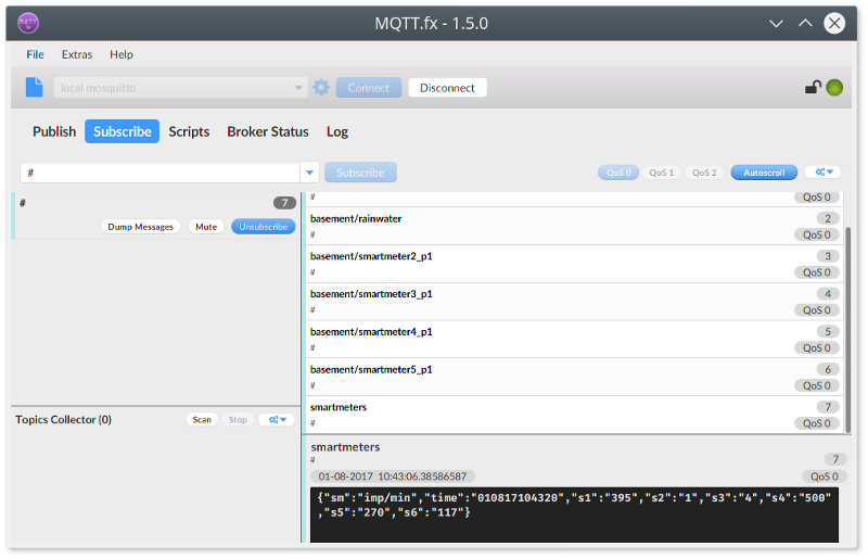
For testing and debugging you can use the cool MQTT.FX software. It's a JavaFX based MQTT Client based on Eclipse Paho an very comfortable for testing purpose. Downloads on http://www.mqttfx.org.
An alternative softaware is mqtt-spy.
SmartyReader to read 5 or 6 Smartmeters
A little board to read one smartmeter exists here.
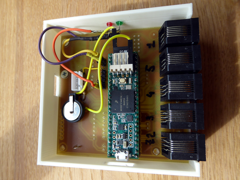
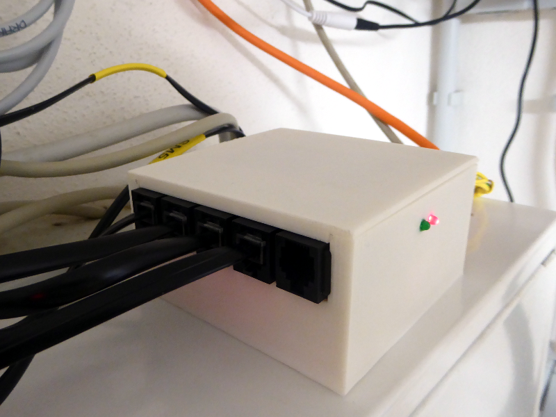
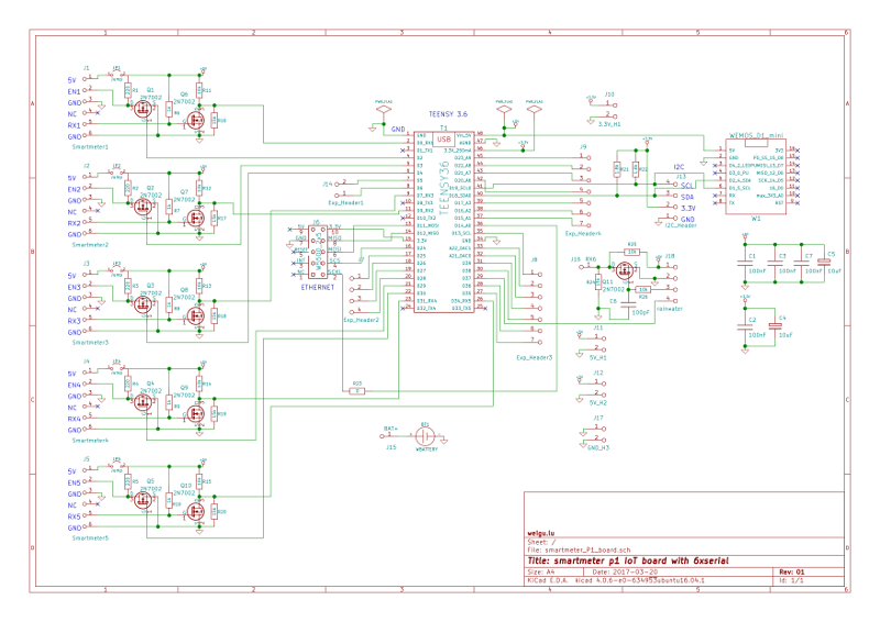
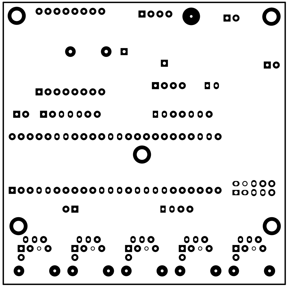
A second board with a Teensy 3.6 microcontroller was created to read 5 smartmeter and serial data from my rainwater tank (Teensy 3.6 has 6!! serial ports). I use a chinese W5500 board to connect to the net (2x5 pin Ethernet header).
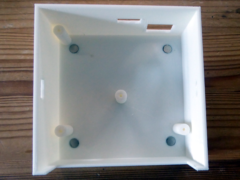
The housing is designed with blender and uses 4 strong magnets with 6 mm
diameter (stl and blender files in Downloads).
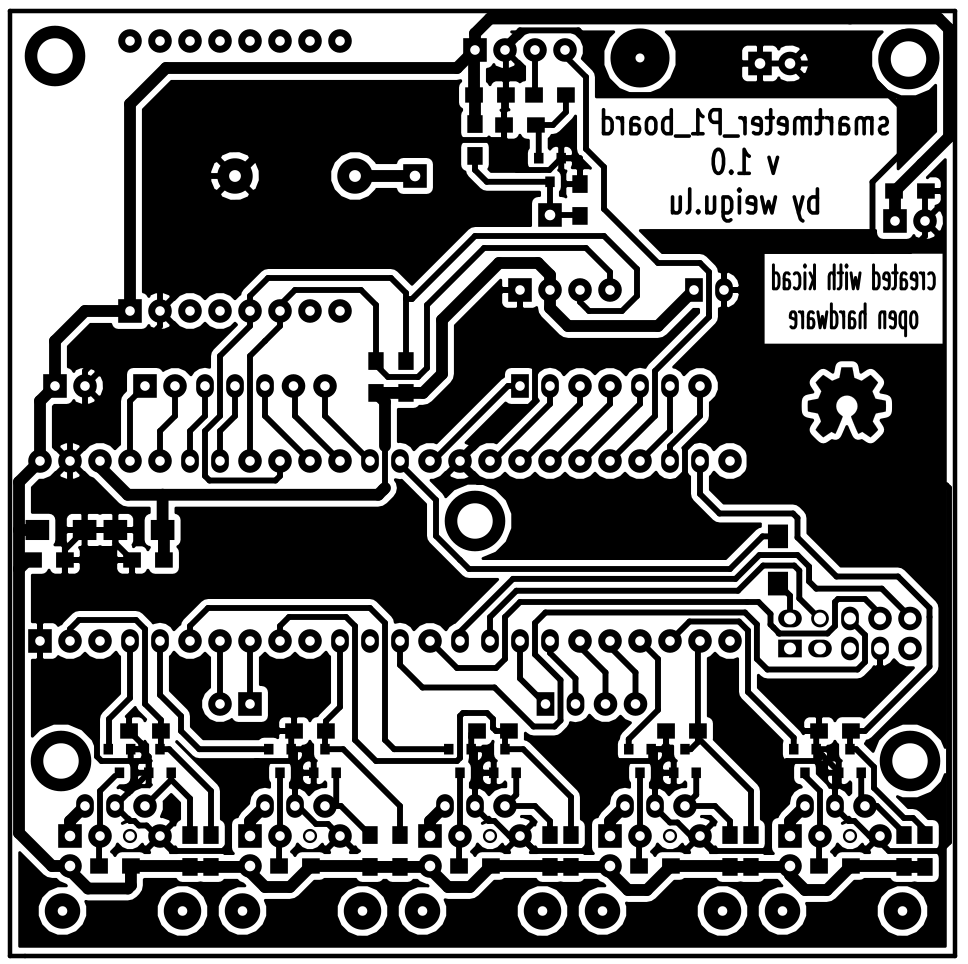
Circuit and PCB
The PCB is one sided.
